An Artifact of Innovation: The Hamilton/Buren Intramatic by John Davis May 21, 2001
Part II
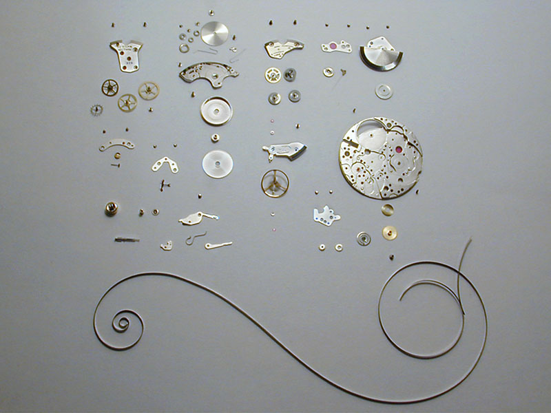
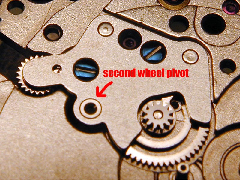
In this examination of the architecture of the Hamilton 628 (Buren 1280), I will trace the many pieces of the movement in the order in which they are replaced into the movement during servicing. Typically this order would consist of: the power train, the barrel and barrel bridge (including the click, ratchet wheel and crown wheel), the escapement, the keyless works and the motion works, followed last by the automatic system. One of the many peculiar details of this movement has the pivot for the second wheel (with its offcenter cannon pinion) in the motion works bridge. As the second wheel is the first wheel in the power train (the barrel being the literal "first" wheel), we must first install the motion works bridge before we can assemble the power train.
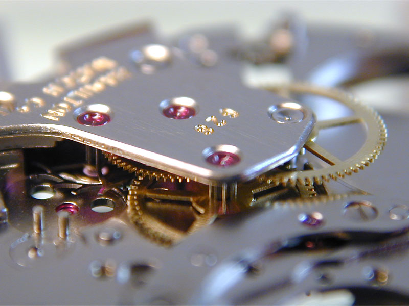
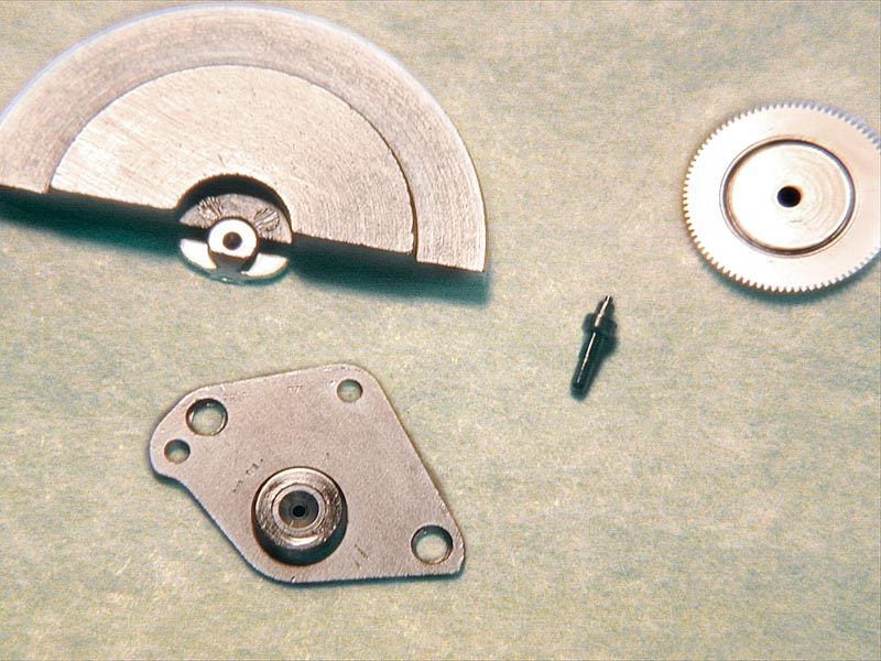
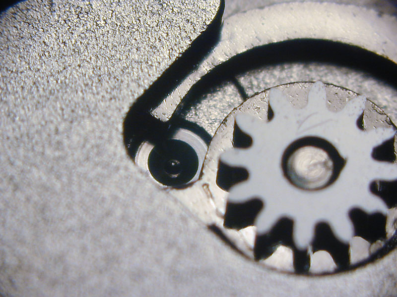
Many movements that I've seen from the 60s and 70s feature offset cannon pinions. While traditionally the second wheel is located in the center of the movement (and often called the "center" wheel), manufacturers found that a direct center seconds layout was sometimes facilitated by placing the cannon pinion outside of the center of the movement. By moving the second wheel out of the center, a flexibility in the gear train layout was realized that helped to create thinner, more complicated movements. An offset cannon pinion typically drives the minute wheel (of the motion works) and applies power directly to the intermediate wheels in the keyless works, which can be a source of drag and stoppage in neglected or over lubricated movements. A major disadvantage of an offset cannon pinion from a servicing standpoint is that if it needs to be tightened (lanterned), the entire power train must be disassembled to do so. Because the second wheel in the Intramatic is pivoted (on the bottom) in a bridge that secures the minute wheel and intermediate handsetting wheels, we must assemble this portion of the top plate before we can proceed with the power train. It does not seem incredibly smart to me to place the pivot in a moveable bridge (a little shift one way or the other would be a bad thing) but it does seem to work fine. You'll notice the spirally skeletonized minute wheel. I'm not sure if this is supposed to give the minute wheel a bit of flexibility (this seems doubtful) but the cutout does facilitate oiling the third wheel pinion.
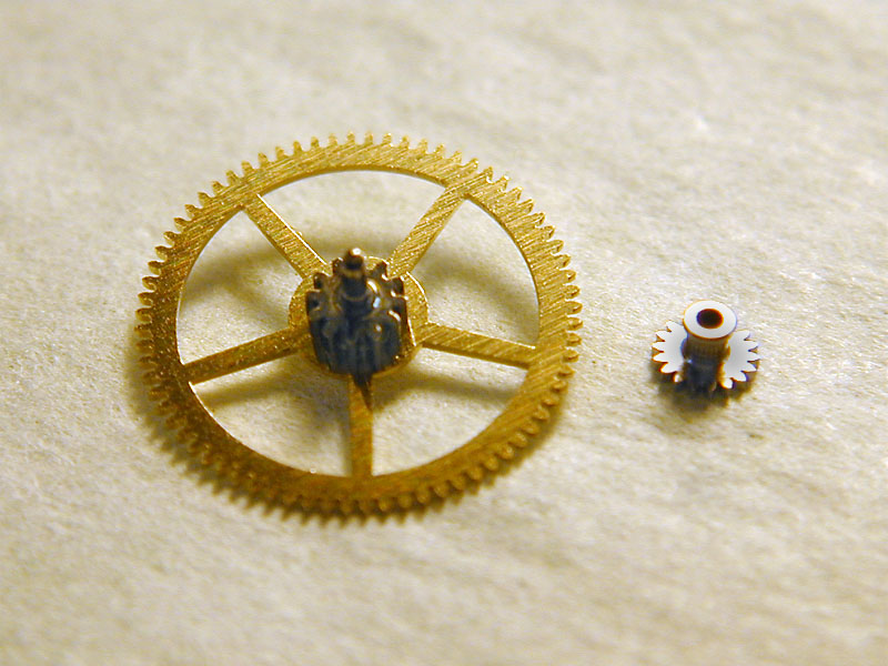
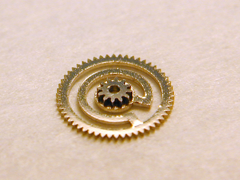
 The first intermediate wheel for the handsetting function resembles two wheels laid one on top of the other. This is part of Buren's patented no-slip handsetting mechanism. What I believe this means, is that the smaller teeth on the upper portion of the first intermediate wheel allow for less slop in the handsetting action,
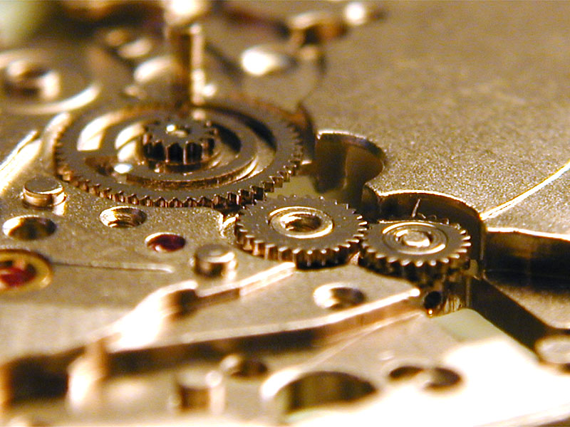 thereby insuring less lag time between when the hands are set and when they actually begin turning again. Regardless of the effectiveness of this patented system (assuming I even understand its intended purpose correctly), it is refreshing to see an innovation in a watch movement that clearly increases its expense in the interest of improving its performance. The skeletonized minute wheel is another example of Buren's willingness to raise production costs in the interest of advancement (whatever the goals of that particular bit of artistry might've been).
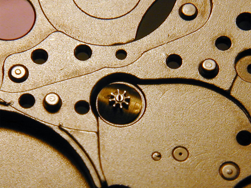
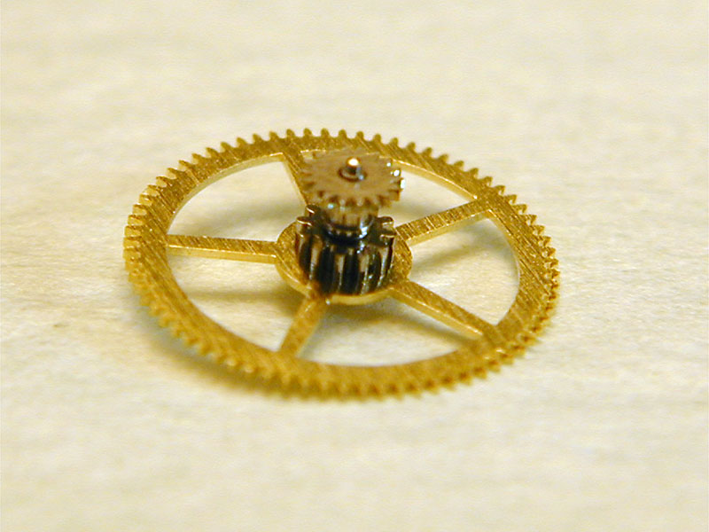
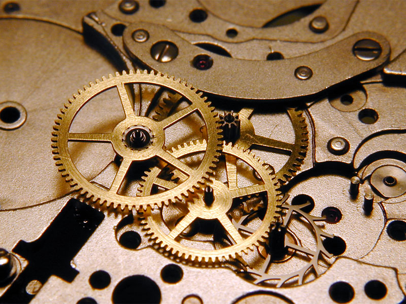
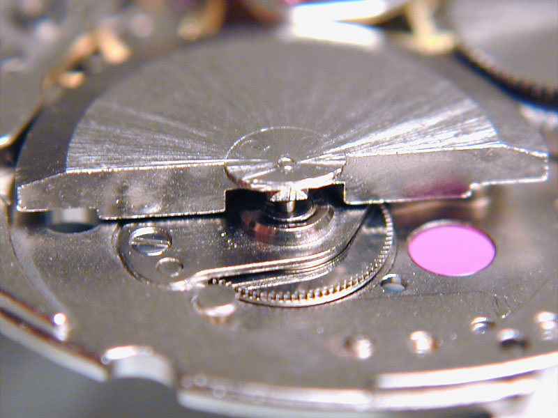
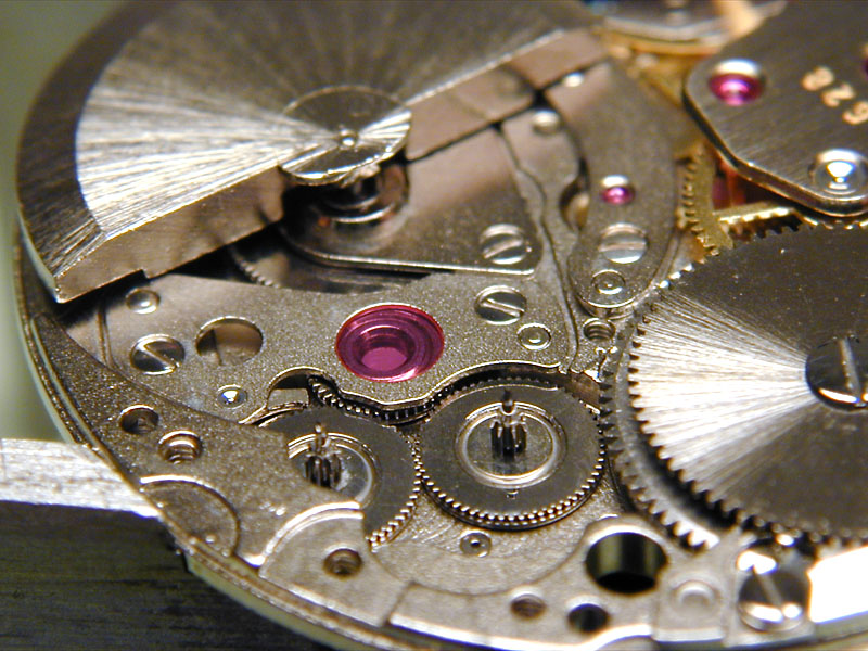
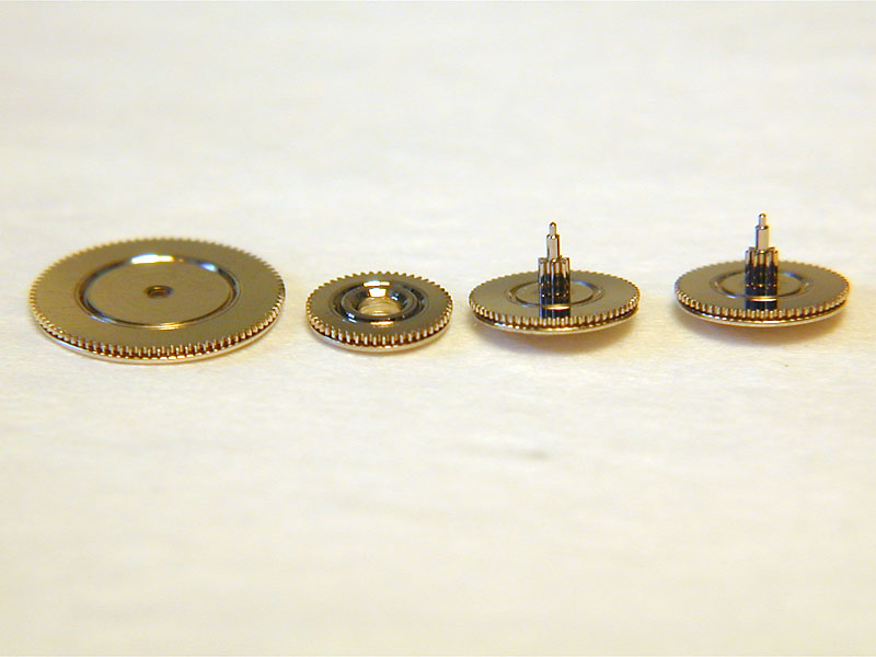
After assembling most of the motion works (the intermediate handsetting wheels, minute wheel and the associated bridge) we can turn the movement over and focus on the power train. A curious design feature of the Intramatic is that both the seconds and minutes are driven indirectly. A small center seconds pinion with it's own bridge lies underneath the outermost sweep of the rotor and is driven by the third wheel directly (unlike the traditional indirect center seconds layout where an auxiliary third wheel is used). The center seconds pinion is tensioned slightly by a thin copper washer (very similar to a dial washer) to reduce the jerky motion sometimes exhibited by indirect seconds movements. A weakness of this design is that it allows for no flexibility in how much tension is being created by the washer. I suppose it could be removed and bent more or less to change the tension but this seems a bit troublesome once the movement has been fully assembled. The center seconds pinion is unjeweled on the mainplate but is thankfully jeweled on the topside where the washer's tension is focused. The rest of the power train is appropriately compact and the wheels and pinions are functionally finished.
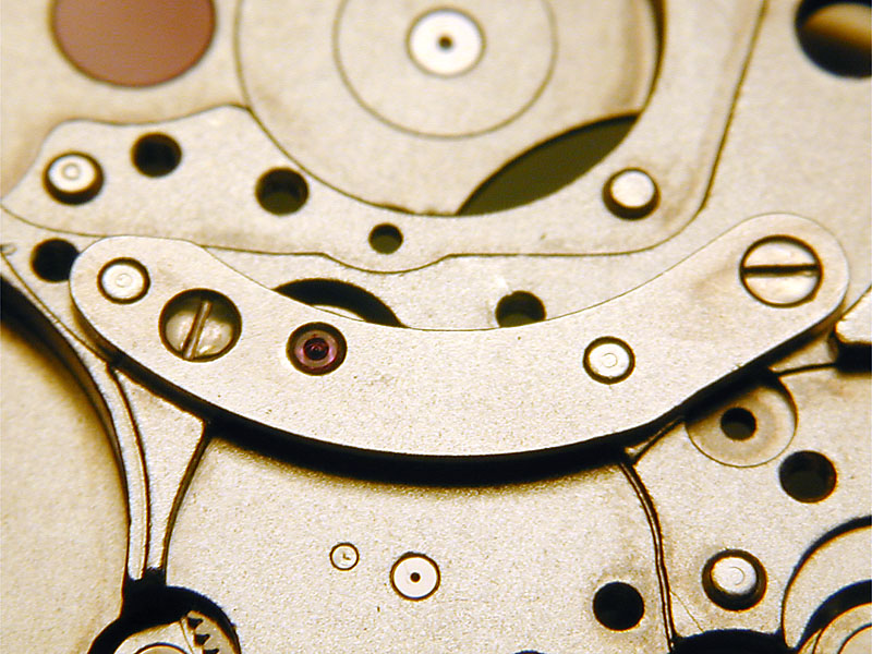
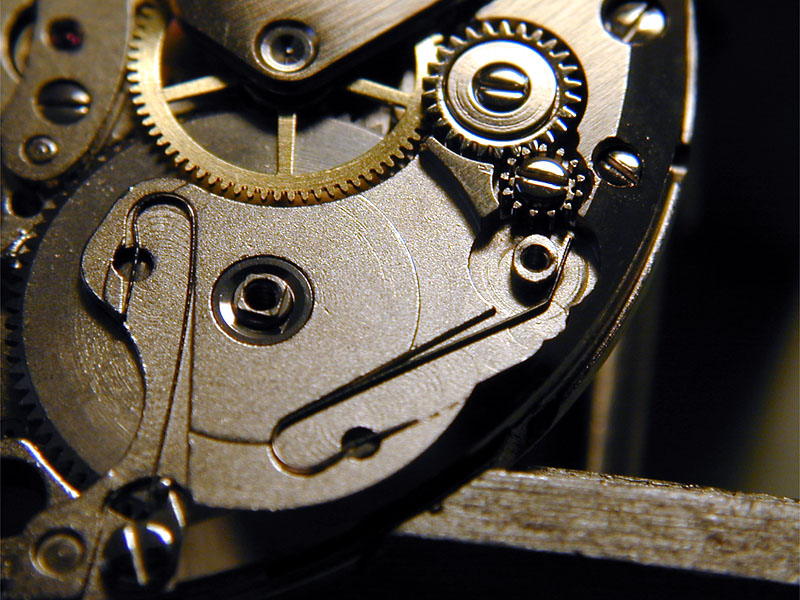
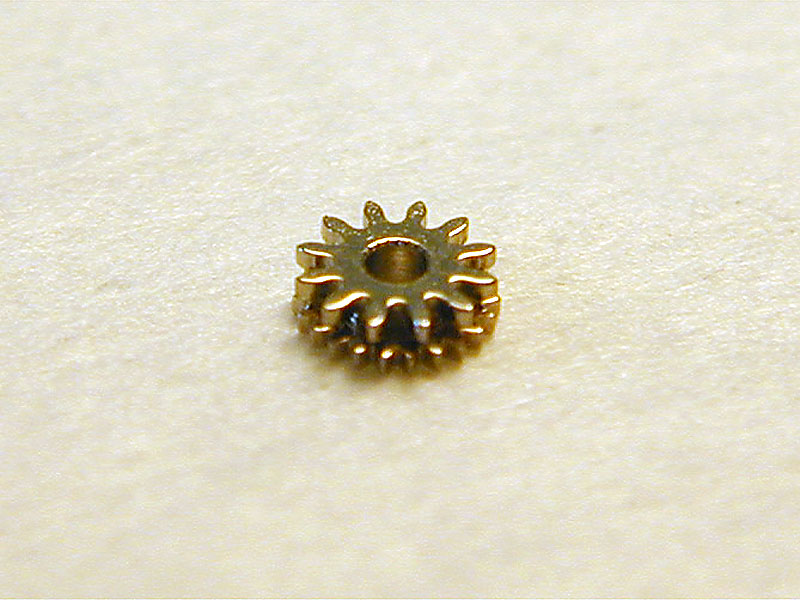
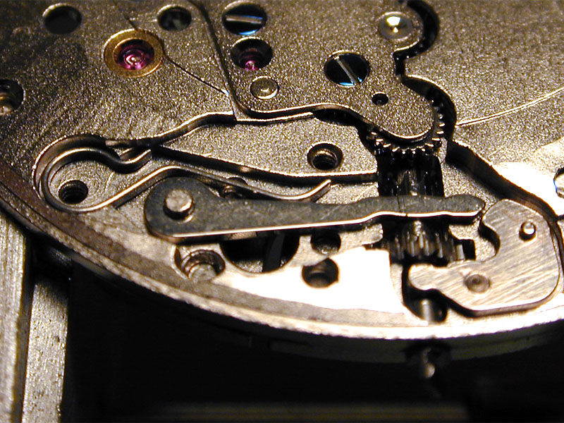
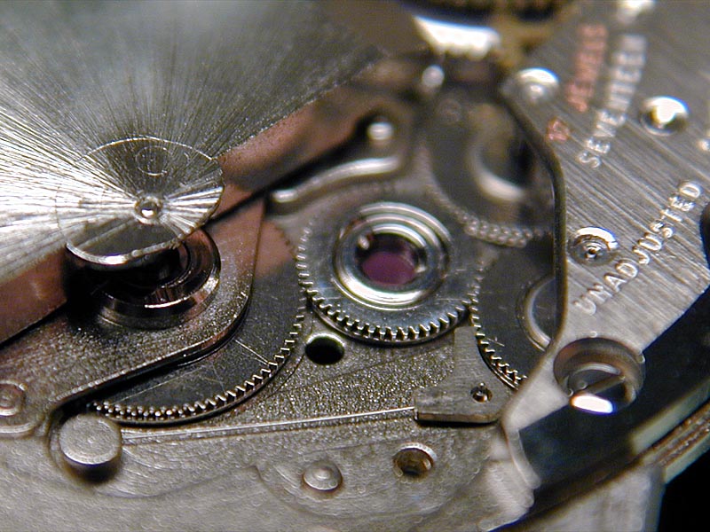
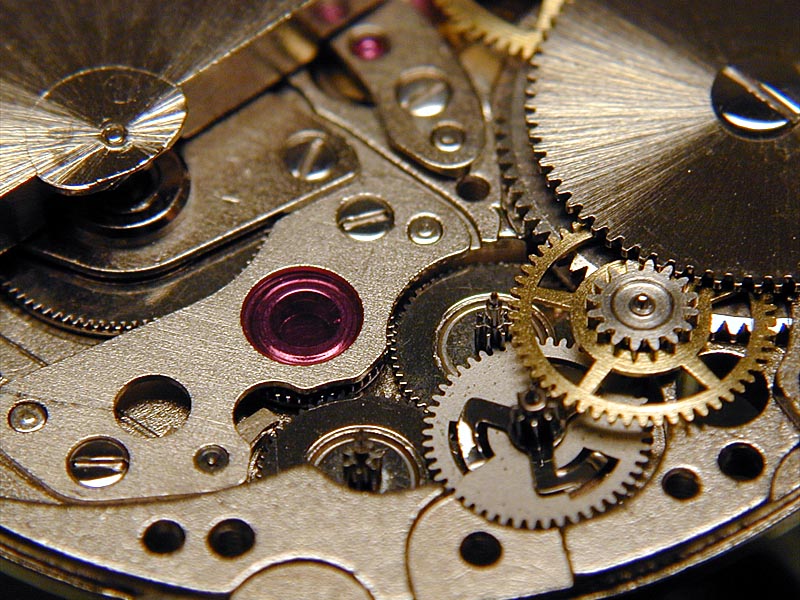
Next we move on to the barrel bridge. Here we encounter even more evidence of the design creativity used to properly implement the micro-rotor winding. In order to achieve maximum power transmission from the rotor, the manual winding gears are decoupled from the click wheel when not in use. The barrel bridge contains two extended wire springs which operate the click and the manual wind decoupling (left and right in the photo respectively). The small crown wheel meshes with an intermediate winding gear that further exhibits Buren's willingness to increase production costs for the sake of design functionality (or so it would seem). This little gear is shaped like a tiny column wheel and is assuredly almost as expensive to make. This intermediate gear engages with another that is pivoted out of the way of the click wheel when being wound by the rotor. It is otherwise held in contact with the click wheel by an elongated, wire spring with a dogleg at the end. The wire spring interacts with a smooth channel on the underside of the second intermediate wheel, making it taller than it would be otherwise and hence the extended teeth of the first intermediate wheel to properly enmesh with the pivoted gear (notice the ellipse-like post it floats on). The significance of this arrangement is that the automatic system does not have to rotate the crown wheel when winding the click wheel. A more efficient system would have the manual winding gears decoupled completely unless they were being used. I've seen such a system in other watches and I believe that Buren used it in later incarnations of the Intramatic.
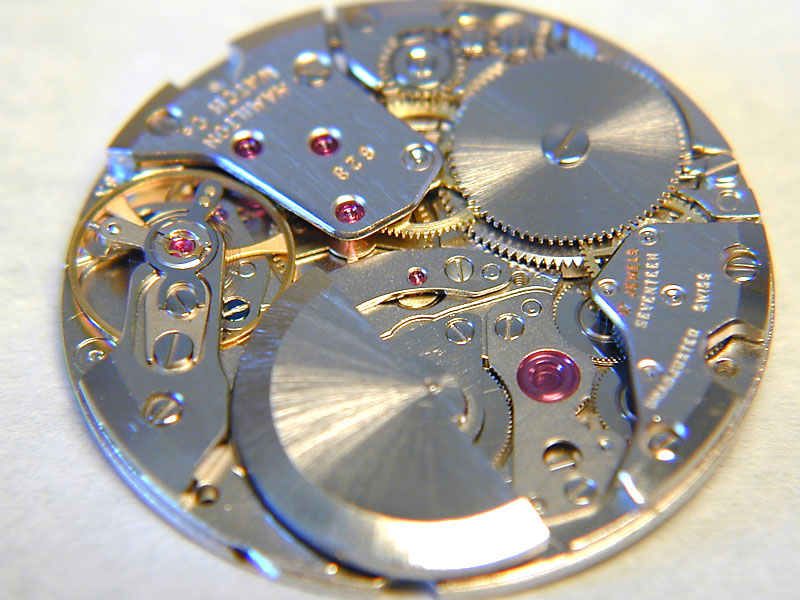
From here we turn our attention to the escapement. After assembling the other functioning portions of the watch, it's a good idea to assemble the escapement and see if it runs before addressing any issues with the automatic system, motion works or calendar mechanisms (not to mention repeater or chronograph modules). In this way, any issues with the power train, barrel of escapement may be addressed without disassembling any additionally systems/complications. The Intramatic is particularly friendly in this regard though. One major advantage (during servicing at least) of the micro-rotor design is that all the related mechanisms on the top plate of the watch may be accessed without disassembling or removing others. In this case, the choice to address the escapement first was not only one of habit, but also intended to save the most interesting portion of the movement (the automatic system) for last.
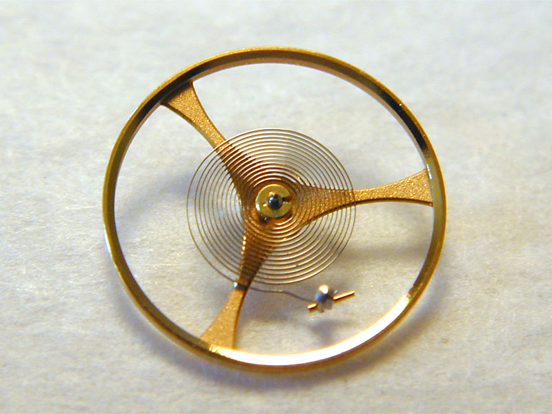
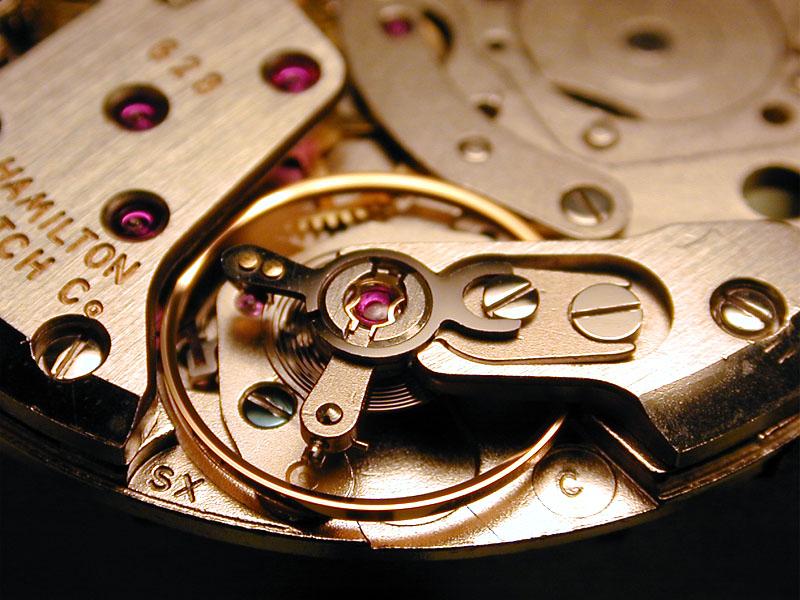
The escapement of the Intramatic is entirely ordinary in most regards (for its time). It has a three spoke Glucydur balance (notice the scalloped arms of the balance wheel) and a Nivarox hairspring (these components were all but necessary for the time, when chronometer trials were a very real, well advertised challenge). The hairspring is flat and without a proper dogleg even (a feature once thought to be a compromise to account for the curb pins, now understood to be beneficial to positional performance). I was tempted to put a dogleg in it but decided to respect the integrity and history of the design rather than attempt to improve its performance (I've done it before, don't try me). What is remarkable about the escapement is the semi-fine regulator and beat adjustment (patented Isochron system). This is an elaborated version (actually un-simplified to be historically accurate) of the Etachron semi-fine regulation system found in most modern ETA movements (developed by Eterna?). The Isochron system employs two sets of eccentric screws and forked levers to manipulate the curb pins and stud carrier separately and with great accuracy. This allows the adjuster to put the watch into near perfect beat and regulation without many frustrating back and forth movements of the regulator (curb pins) and stud carrier (if the stud carrier is even movable, as it typically is fixed). Also visible is the Incabloc shock protection that is one of the more user-friendly systems yet devised.
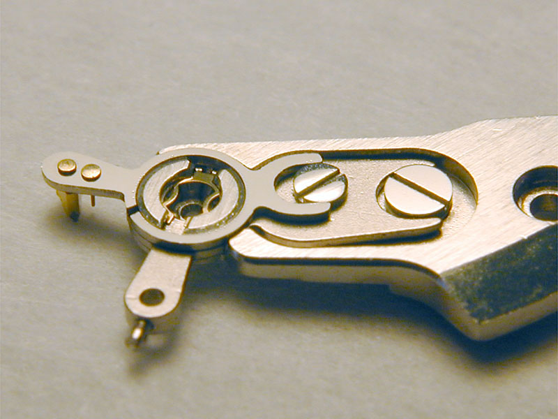
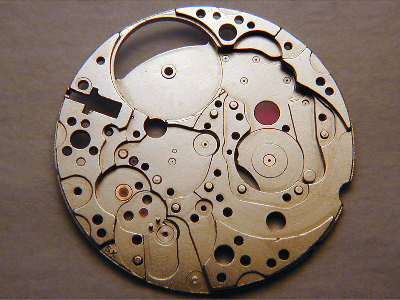
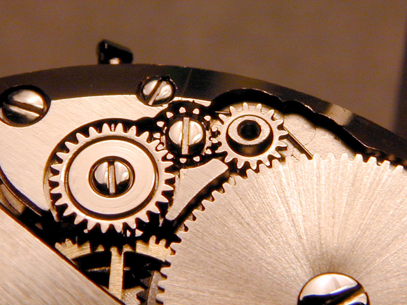
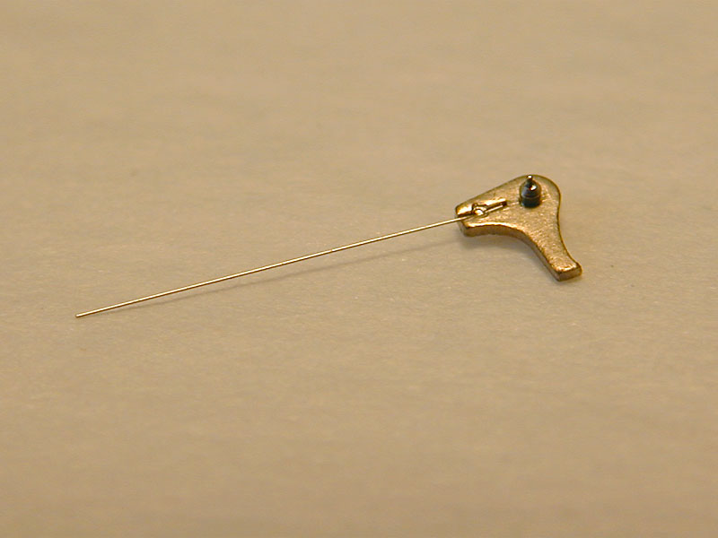
Before we finally turn our attention to the automatic winding system, let's address the keyless works (they look like this, notice the groovy shaped wire spring) and the motions works (sorry, no picture, I guess it was pretty boring). Of note is that the mainplate shows signs of a calendar mechanism that is not present in this model.
OK, on to the automatic system. The defining feature of the Intramatic movement might also ironically be its Achilles heel (at least in this incarnation). The micro-rotor itself is mounted in such a way that wear on its bushing is inevitable. I've heard many stories about Hammy micro-rotors that rattle and this one was no exception. I'd guess this is one of the first holes to be jeweled in the versions of this movement with higher jewel counts (this one only has 17 jewels as opposed to some with 21 or even 30 jewels). The winding mass is mounted on a staff that passes through a bushing in the rotor bridge where a good-sized gear is mounted close to its lower pivot. The geometry of this setup puts a lot of stress on the upper bushing and the creative depthing insurance measures employed in the transmission of power to the automatic reduction gears (I'll get to that in a moment) only increases the tendency to wear unevenly. The example I serviced had worn to the point that the rotor was rubbing the mainplate but it was easily remedied by closing the hole a little on a staking set. More significant wear (or a desire to upgrade the movement) would've dictated jewelling the hole (not something I'm frankly comfortable trying on someone else's watch yet).
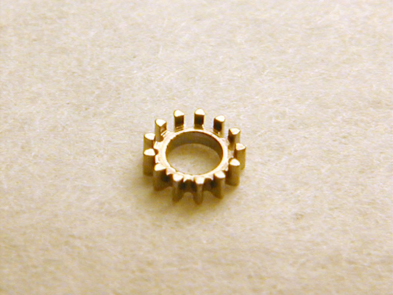
One of the most interesting (and more visually striking) elements of the automatic winding system is the floating (swimming, gliding, free) pinion between two huge jewels. This is a stubby little doughnut of a pinion that floats between two large solid jewels and performs the direction switching that allows the Intramatic to wind in both directions. I've sharpened up my crayons in an attempted to illustrate this action in these two drawings. The floating pinion bridge (6) with its large jewel is transparent so that the action of the pinion may be observed. The switching gears (2 and 3 in the drawing) are enmeshed and always rotate so that the lower gear is spinning clockwise and the upper gear is spinning counterclockwise. In fact, the click (5, in black) ensures that they cannot spin the other way. When the rotor (1) is spinning in a counterclockwise direction (as in the first drawing), the floating pinion (4) spins clockwise and is forced into contact with the upper switching gear which it propels in a counterclockwise direction. When the rotor is spinning clockwise, the floating pinion spins counterclockwise and is forced into contact with the lower switching gear which it propels in a clockwise direction. The upper switching gear's pinion is enmeshed with a reduction gear, which in turn transmits the winding power in one direction only. For manufacturing simplicity both of the switching gears have an associated pinion but the pinion on the lower gear serves no function. I promise that next time I'll try to use an animation to demonstrate instead.
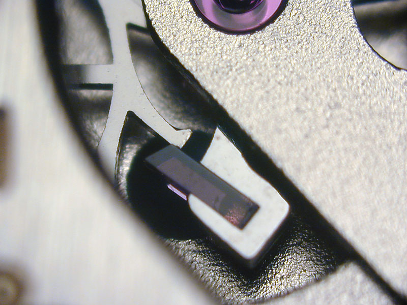
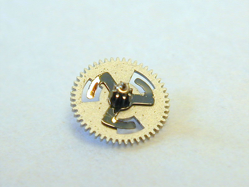
The problem with this arrangement is that the floating pinion necessitates measures to ensure that its teeth are properly engaged with the rotor and switching gears. Without such measures the teeth of the interacting gears would bind or wear very rapidly. Buren's clever solution was to place a smooth roller on the underside of each of these four gears that is exactly the same size as the proper depthing radius of the gear teeth. The problem with this solution is friction. The smooth roller interactions greatly reduce the efficiency of the power transmission, as a cumbersome degree of rolling friction is present at every single turn of the rotor. This friction also places additional stress on the rotor's shaft and bushing. JLC's rocker switching design is much more efficient in this regard, as are the irregular cam designs employed by Seiko, IWC and now, LUC, in their bi-directional automatic systems. The decoupling mechanism for handwinding is a three armed "swastika spring" mounted on the last reduction gear of the automatic system. This spring is attached to the pinion and can turn more or less freely (without turning the gear that is mounted on the same arbor) when the watch is being handwound, but locks and transmits power to the pinion when the rotor is spinning.
I'd very much like to take a look at later implementations of the Intramatic and see how these issues might've been addressed differently (or not). I'd also like to take a look at one of the highly jeweled models, heck I'd like to own one I think. Micro-rotor movements are aesthetically much more pleasing to my eye and Buren can be proud to have been the first company to introduce them to the watch buying public. Despite the obstacles that had to be overcome, they succeeded in making a very thin, very accurate automatic movement by employing revolutionary mechanisms that functioned reasonably well in a variety of different levels of execution and elaboration. As a classy example of a turning point in the history of both Hamilton and automatic movements in general, a Buren powered Thin-O-Matic makes for an interesting, horologically significant addition to any watch collection.
The movement for this article was kindly provided by Kent Lee. Thanks are due to Tim C. for sharing his experiences with this movement with me.
All Rights Reserved
